- Mold segment -At least one of the faces of mold segment, which is a separate body should be in contact with the casting.
- Parting direction of a mold segment is the direction generally along the axis of the mold segments and is introverted from the adjoining mold segment. Draw direction is the other name of parting direction.
- Draw distance is the minimum distance traveling required to completely separating one mold segment from the adjoining mold segment.
- Parting surface is known as the surface of contact within any two segments of the mold.
- Parting line is the line where parting surface meets with the casting surface of the mold.
- Undercut - In reference to the parting direction and parting line, undercut obstruct s the withdrawal of the part from the mold. Using a consequent shaped core, an undercut characteristic is produced. Hence, higher costs of special materials, additional tooling and lower productivity are involved.
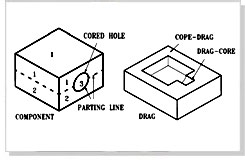
Parting surfaces are further classified on the basis of mold segments (such as cope, drag and cores) at the interface. They can be categorized as cope-drag, cope-core, drag-core and core-core parting surface. Only cope- drag interface is referred to the parting surface during practical applications.
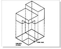
The parting line is supposed to coincide with the estimated borderline of the casting when viewed along the draw direction. To attain the parting line, the corners of the castings are projected perpendicular to the plane in the parting direction. Also, the outermost boundary's perimeter is considered overlooking the innermost sections of the projected corners. This is anticipated back to the casting and the respective landing points are estimated. Then these landing points are joined to each other in the same order to form parting line. Multiple substitutes of parting lines are required to be figured out in case of multiple landing points. These alternatives of parting lines are able to generate flat, stepped or complex parting lines in reference to the shape of the components.
 In ideal conditions, parting line should be a straight and leveled plane. A logical study of the part design will promote the most efficient method and location of the parting line. At times, part designs causes special gate designs and in such cases reverse parting lines are used. When part lines initiate special mold designs and construction, multiple parting lines are generated.
There may arise some situations where the meaning of the parting line is required to be stretched. The design of the three-plate mold is an example of such situations.
Shut off areas There might arise many more cases where mold components come together to form a seal while molding the final product lines. And these areas are known as shutoff areas. Primary parting line is the most common shutoff area seen in the patterns, mold and core designing. Shutoff areas may be divided further into horizontal, non-horizontal and vertical shutoff areas